How to assemble the board.
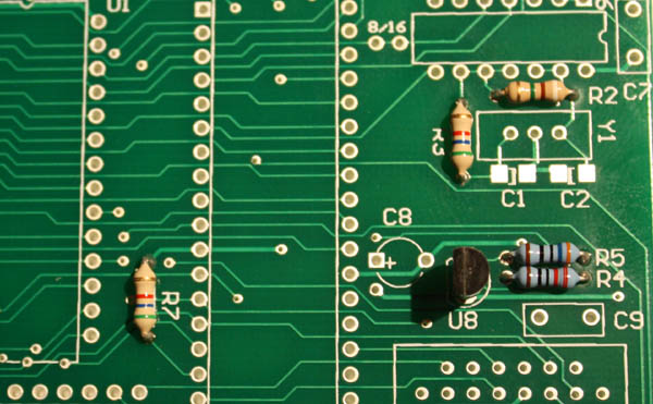
Start with the resistors. It is very important to use the right ones
for R4 and R5 or the CPLD
may go up in smoke. Note the color codes on this close-up.
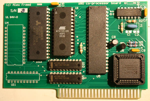
You only need the sockets for the CPU if you plan to replace it with an
even faster chip. It is a tradition to use sockets for PROM chips to
make firmware updates easier. The firmware on this board didn't change
in almost 30 years so there is not much risk involved. On the other
hand someone may come up with enhanced firmware. 62K out of 64 are not
used.
I have only tested the board with 10 MHz Z80 chips and a 10 MHz
oscillator. In theory it should work faster if one uses a faster
CPU and clock. I don't have any plans to break records here.
The original PCPI board worked at 6 MHz, but there was a dirty secret:
an extra wait state was inserted on M1 cycles, so the real speed was
some 15% slower. Twice faster is good enough for me.
Assembled board. A quartz crystal used here, so C1 and C2 are installed
- 22pF each. You will likely use the resonators that come with the kit
unless you want to experiment with running at a higher (or slower)
speed. Z80 CPUs
up to 20 MHz are available .
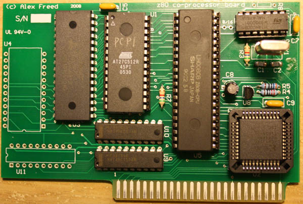
One more assembled board. The stock 10 MHz oscillator used, no
capacitors are needed. No socket for the CPU is needed either. Note
that the XILINX CPLD is "upside-down". It is very easy to insert it the
wrong way. The one cut corner doesn't really stop you from doing it.